Video of the auto-deployment (691 kB, *.mp4, MPEG-4 H.264) 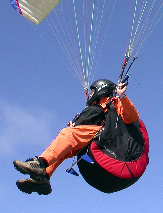
Video of in-flight activation (910 kB, *.mp4, MPEG-4 H.264) |
|
Video of the auto-deployment (691 kB, *.mp4, MPEG-4 H.264)
Video of in-flight activation (910 kB, *.mp4, MPEG-4 H.264) |
I invested much personal time (and money) towards achieving a better speedbar design because of disapoinments with available designs. See Market Comparison. My guess is that I spent 250 hours on this project so far (2005/12/15). This page is to share the knowledge learned along the way.
Pilots are free to use the ideas shown here to build a similar unit for themsleves. If someone wants to mass produce this design, that should lower the purchase price for buyers. All I ask in exchange is a small recognition fee as the inventor (I'm easy to negotiate with). In the meantime, I will hand-craft one unit at the time for those who immediatly want to purchase (Price) this speedbar.
This used to be a long list, now it is simple:
Who is this design for? There are many different "ideal" speedbar designs according to the rest of your equipment setup. This design is best suited for pilots who:
It only made sense to provide a new design, if there could be improvements over what is available on the market.
This Excel spreadsheet shows the advantages over existing speedbar designs.
The J-Rod: Think of it as the "Hot Rod" of speedbars. It is designed to best match a list or requirements (see Market Comparison). Low production and hand-crafted.
The price (subject to change) is
248
$US
+ packaging & shipping.
Payment must be made in advance.
Send me an email to place your order.
Thank you for supporting better product development.
Price justification:
I have to make it worthwhile for me to build one unit at a time for pilots.
Materials are cheap, I will guess at about 20$.
There is fuel and driving+shopping time to get the parts.
But the big thing is my personal time to do the manufacturing work.
I'm guessing 2.5 hours of manufacturing work at this time (until I find shortcuts).
Difficult to price my personal time away from my wife on evenings and weekends,
but I am setting it at 75 $/hour.
All the time I spent researching and developping this product is not part of the price
as I did it all for myself, following my quest of better equipment.
So: 188 (2.5 hours times 75$)
+ 20 (materials)
+ 40 (acquiring materials: fuel, driving and shopping time)
+ 0 (250 hours of research & development)
--> 248.
You can Build It Yourself for your personal use.
The best thing to happen for everyone...
Would be for someone to start manufacturing this product in Europe (where most PG pilots are)
and distribute from there.
Price would be reduced for buyers,
I just ask for a small inventor's fee on each unit (I'm easy to negotiate with),
and the manufacturer would make a profit.
If you know someone who wants to manufacture this product,
now is a good time to start discussing this.
Please put me in contact.
Pilots who purchased:
Pilots who followed the Build It Yourself instructions:
Others:
|
|
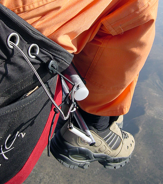
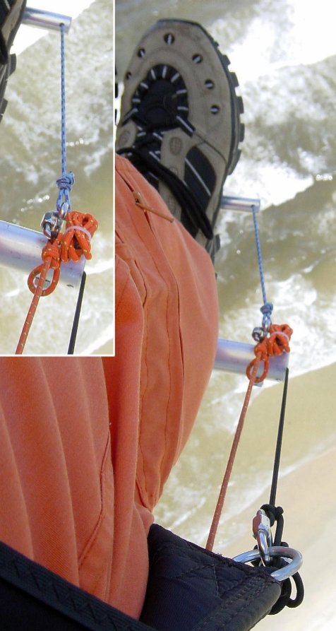
2006/4/15. In flight. |
|
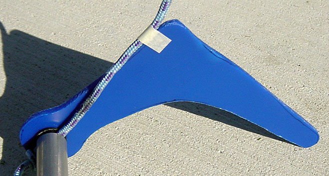
This graphically demonstrates why a small forward displacement of the first step, makes such a significant difference in ease to grab it with the foot. |
|
|
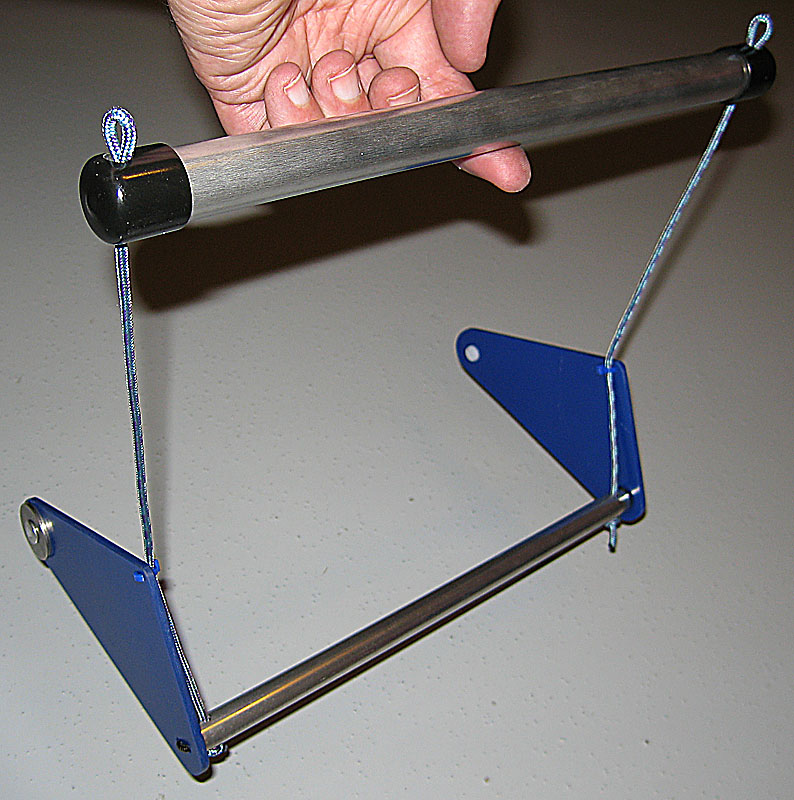
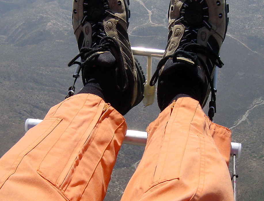
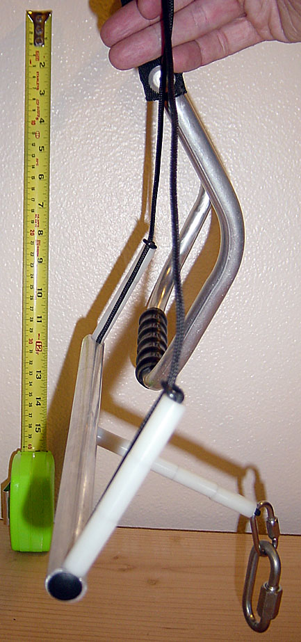
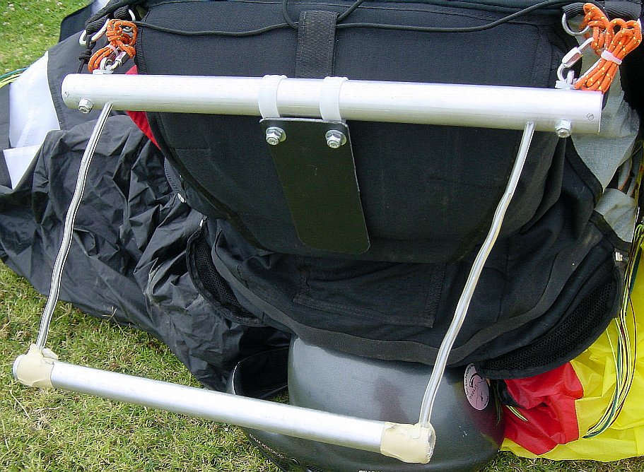
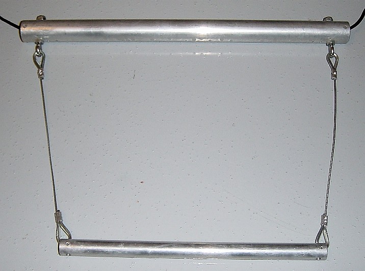
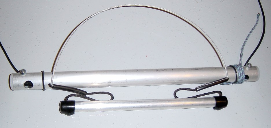
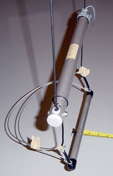
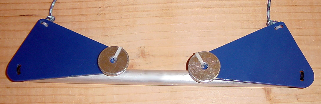
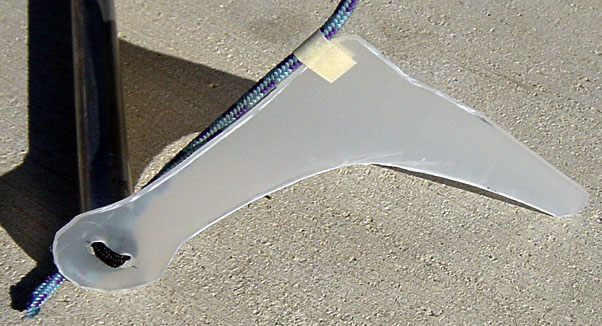
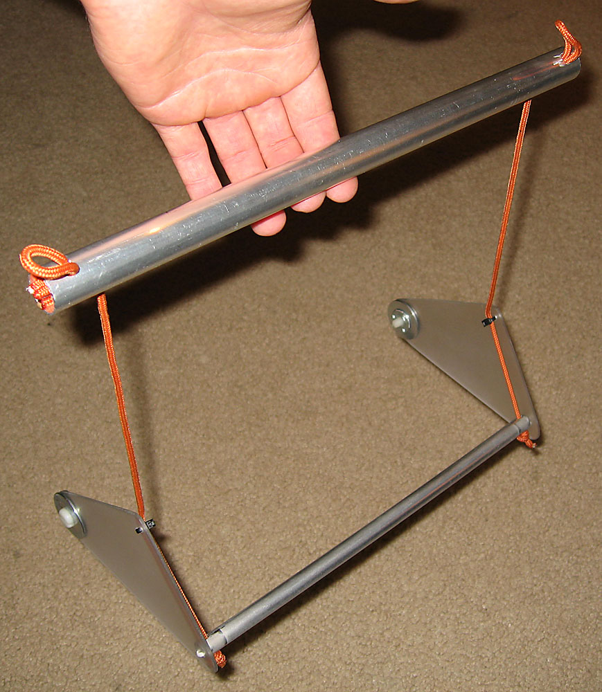
2006/11/24. Global view. Total weight is only 165 g (5.8 oz). |
|
|
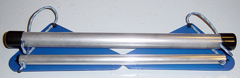
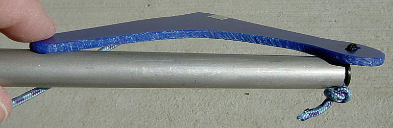
2005/12/10.
Fins folded for compact storage.
Notice how the tail end of the fins meet perfectly, without overlap.
Update needed: Picture to show relocated (closer to main bar end) line going to the first bar. |
|
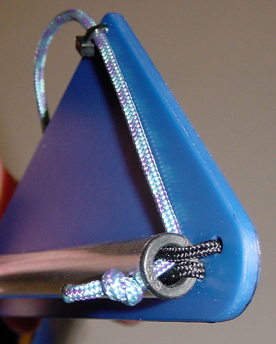
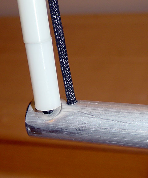
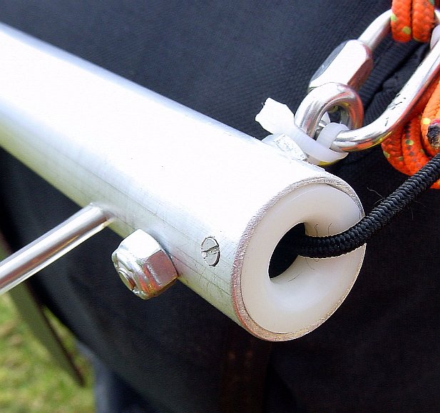
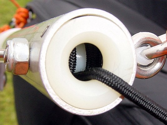
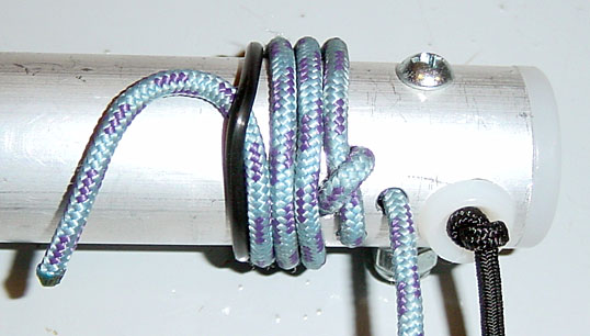
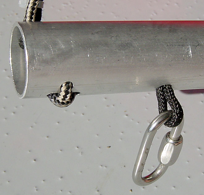
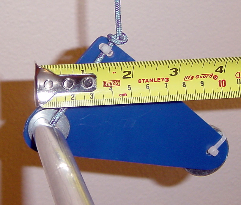
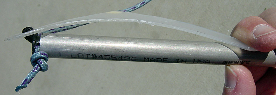
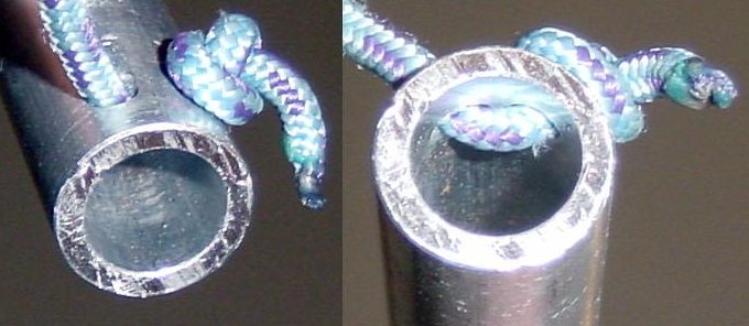
2005/12/10. Detail of the end of the first step bar. Rotation of the fin is limited (desired effect) by the 2 bungee lines on either side of the load line (blue). |
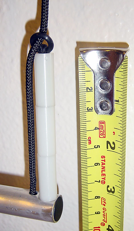
| 2005/11/24. Bar length. It was found that a free span of 23.5 cm is required to comfortably apply both booth soles. To this span is added 0.65 cm (1.5 mm cord radius + 5 mm hole axis from end) at each end, for a total length rounded to 25.0 cm. Note: The effective load span (between line axis) is 24 cm. | |
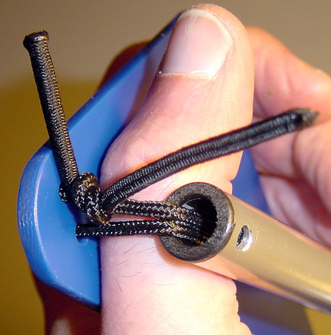
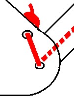
| Decision matrix (Excel spreadsheet) | 2005/11/9. Finding the best way to connect the line from to the main bar onto the 1st step's bar. The "Simple_InOut_2" concept (picture) is chosen as the best. |
| Decision matrix (Excel spreadsheet) | 2005/11/11. Finding the best way to compress/center the end fins onto the bar ends. The "SingleBungee_OutInFin" concept (schematic drawing) is chosen as the best. |
| Bar Material Selection (Excel spreadsheet) |
Bar material selection.
All other parts related to this bar have been designed with the consideration
that this bar's cross-section dimensions can change without significant re-design work.
|
Dimension optimization (Excel spreadsheet) |
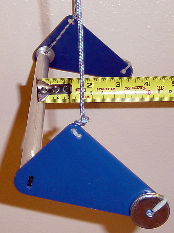
2005/12/2. Study of optimal overall dimensions between the forward displacement of the bar, and dimension to the point where the line is held. Selected dimensions: 4.0 cm forward first bar, with Theta = 35°. |
|
2005/12/6.
Design parameters:
|
2005/12/9.
Materials:
|
|
|
2005/12/15.
Counterweight: 14 g (0.5 oz) needed with 2005/12/10 design.
|
|
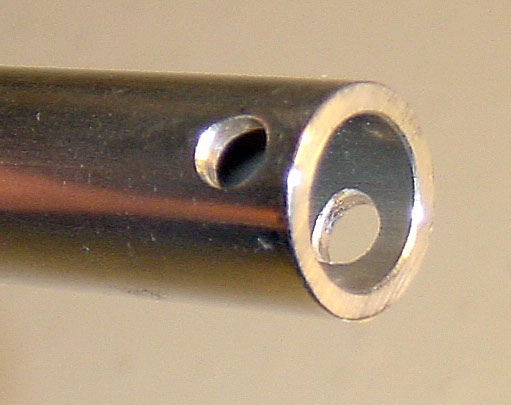
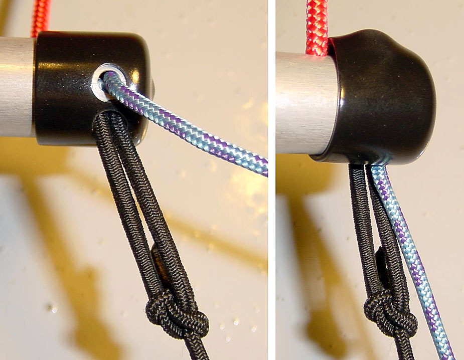
2006/11/24. Top view of the bar end. |
|
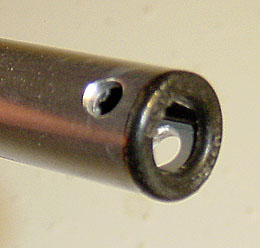
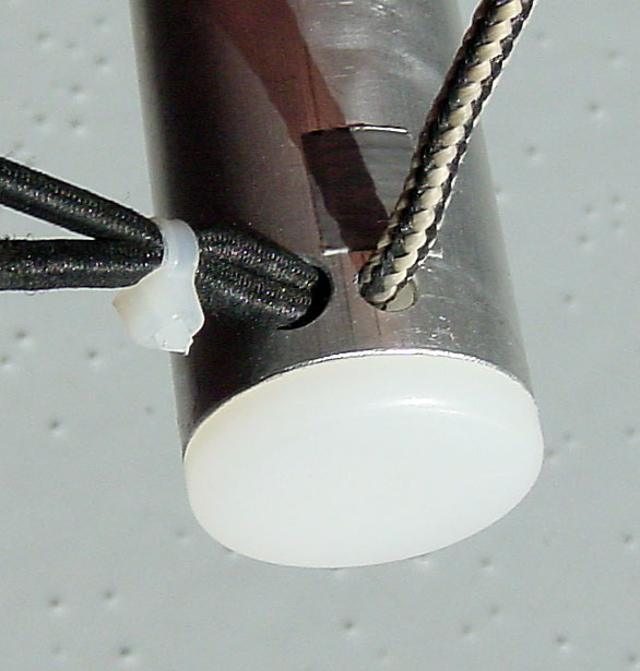
2006/11/24. Bottom view of the bar end. |
Retraction system
Why you want one: Bars are retracted for easier running on the ground.
Did you ever see a pilot trip on his own bar?
Some believe it also offers a safety advantage following a
Frontal Collapse (Recovery),
where the loss of tension in the A riser will have it dislodge from your feet,
and swing back extended to the rear bottom of your harness where it can lock.
Although I am a believer in bar retraction systems
(typically an elastic bungee cord that pulls the bar back up)
I also believe it should be integrated inside the harness:
More room for it, and its mechanism does not contribute to the weight to be lifted.
Note that a
Main bar with built-in retraction system
has proven possible.
More harness models
are arriving on the market with built-in retraction systems (not all equally good).
Make sure your retraction system does not rely on riser tension,
and avoid mechanisms you can forget to set like accelerator line cord locks.
In the meantime it is not too difficult to devise your own retraction system
with an elastic bungee cord attached to the main bar
and enough length to allow the extension of the main bar.
The design of this main bar does not include a built-in retraction system,
but is adapted to connecting with the end of an elastic bungee cord of 3 mm (1/8") diameter.
|
2005/12/10.
Main bar length.
For reference, I measured the line spacing (between cord axis) of a few manufactured main bars:
25.9 cm for the Nova standard bar (0.86" OD, 0.035" wall). 26.5 cm for the Sup'Air (0.635" OD) 28.3 cm for the SystemX (obsolete). Feet width spacing: The minimum length for this bar is dictated by: 24 cm line spacing on the first step bar + two ( 2.0 cm distance to bar end to allow for X-Lock holes ): 28.0 cm minimum. Aside from the weight saving (for same strength safety factor) benefits, I found negative side-effects of a shorter bar (see image on the left):
Decision: Respecting the largest minimum (28.0 cm), the length will be changed from the current full length of 38 cm (loaded lines remain parallel outside a Sup'Air Profeel XC2 harness), to 28.0 cm (27.0 cm axial spacing of lines arriving from harness). Note: The effective load span (between line axis) is 27.0 cm. |
| Bar Material Selection (Excel spreadsheet) |
Main bar material.
All other parts related to this bar have been designed with the consideration
that this bar's cross-section dimensions can change without significant re-design work.
|
|
#1:
#2: No picture. #3: 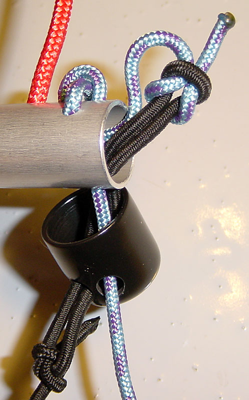
#4: 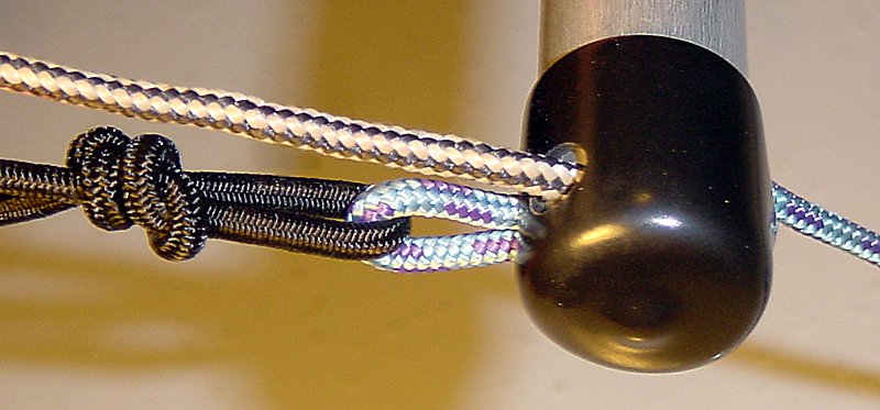
#5: 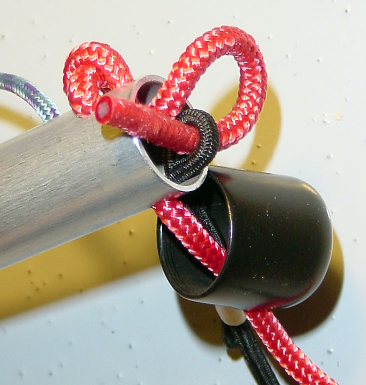
|
2005/12/26.
Main bar interface with harness lines.
From the options listed below, the best compromise was selected for
durability (accelerator and bungee line wear),
easy fabrication,
easy line adjustments/disconnect (no tight knots to undo).
Adjustments are typically limited to when changing wing or harness,
but we still want to avoid having dealing with knot difficult to under after being loaded.
By order of preference:
|
Parts. You should have these:
Tools. You should have these:
Procedure. Follow these steps:
| Please... | Please make a donation, to reward the ridiculous amount of time I spent designing and testing this product. My goal was to demonstrate that a better speedbar is possible, but it would feel good to have your encouragement. It will also motivate me to find ways to reduce fabrication cost for those purchasing a pre-built unit, and make this innovation more accessible to all pilots. |
| Note your start time. | |
| 1st bar: Cut to 25.0 cm. Remove sharpness of ID edge mostly (for easy insertion of "snap-in bushing" later), only removing shards for the OD edges. | |
| Main bar: Cut to 28.0 cm. Remove sharpness of ID and OD edges. | |
| Polish the bars using a de-oxydant made for Aluminum like "Blue Magic - Liquid metal polish". It does a great job on the otherwise typically dull 2024-T4, but produces a messy black residue which needs to be wiped off until the chemical reaction stops. | |
|
1st bar: Prepare end "snap-in bushing", removing the "grips" that normally hold it into a thin plate hole. This will allow to pass a line through the opened space. Also, shave the raised lettering on the surface of the "snap-in bushing" where it contacts the fin. |
|
1st bar: At both ends, drill 5/32" holes through both sides, at 3 mm hole edge distance from the bar ends (or 5 mm from hole center from bar end). Remove sharpness of holes edges (outside and inside of the bar). The hole axis should be parallel for both bar ends (for the same line entry angle). |
|
1st bar: Insert both "snap-in bushing", aligning the openings with the bar holes. |
|
Fins (2): Follow the plan (try printing at 28.5% of size), to :
Cutout the shape for each fin. Smooth all outer edges, using a file. Mark holes, drill with the appropriate bit diameter size (3 different sizes). For Europe, holes sizes must be adapted. Remove sharpness of edges (both sides), mainly where the bungee line needs to pass. |
|
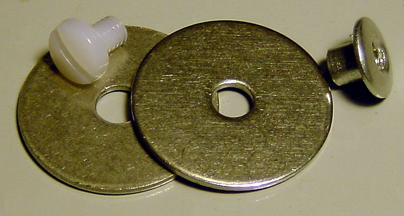
Fin Counterweights.
Cut the Nylon bolts such that they will not protrude the outside
of the female parts of an Aluminum "post with screw"
when 2 washers and the fin are held by them.
Weight: For each fin, the sum of parts for the counterweight is 9 g (0.32 oz) ideally, with 7 g (0.25 oz) as a minimum. When the assembly of the first step is completed, verify that the bottom edge of the fins is horizontal when the first step is suspended. |
|
|
Fin Counterweights. Assemble for each fin, using for each one 2 washers. Use the Nylon head on the side of the fin which will contact the bar, the Aluminum head on the outside. |
|
Fins (2): Use the 1/8" bungee line to compress the fins agains the bar ends, making a square knot in the line that gets sent inside the bar, by passing it through the "snap-in bushing" ID at one end. Don't make this ultra tight, make sure you can pull one fin away by 5-6 cm. Otherwise there would be a higher (unnecessary) bending load on the fins when folded. Only a light compression is needed in flight. |
|
Main bar:
1) On one side (towards the 1st bar), for both ends, make 5/32" diameter hole at 5 mm from the bar end to the hole center. Note: This provides a 27.0 cm spacing for the lines going to the first bar. The ideal spacing allows for a linear width increase from the first bar: 24 cm at 0 cm distance from first step bar, 25 cm [25.0 (1st bar length) + 2x0.15 (flange heads) - 2x0.15 (cord radius)] at 6.34 cm (variable C in "Dimension Optimization" worksheet), 27.17 cm (obtained by linear width increased) at 20.10 cm [22.0 (ideal step spacing) - 0.75x2.54 (main bar diameter)] 2) On the other side (towards harness), for both ends, make 13/64" diameter hole at 6 mm from the bar end to the hole center (or 3 mm margin between the hole edge and the bar end). 3) Remove sharpness of all holes edges (outside and inside of the bar). |
|
|
Main bar: Connection loops. Cut two 14 cm lengths of 3 mm static line. Make 2 knots in them with 5.0 cm spacing after being under tension: about 25 kg (55 lb). Seal ends with a flame. Using a thin cord, pull center (between knots made) through the remaining bar holes, from the inside out. |
|
Bar connection lines.
Cut two 35 cm lengths of the 3 mm static line, and make a tight knot near one end of each.
Seal ends with a flame.
Load those knots by pulling about 20 kg (50 lb) on the line.
Insert the long end of the lines from within the main bar, and outside the holes on the side where they are closest (towards the first bar). |
|
|
|
Main bar: End caps. Using a paper hole punch, make holes to allow for the passage of the connection loops and lines going to the first bar. Thread the connection loop and lines through the holes, and slip the caps on. |
|
|
Bar connection lines.
Pass loose end through the first bar holes, and thread between the bungee lines.
BTW, this is what prevents the fins from freely rotating, when not in flight.
Make knots in the line, under the bar, so that bar spacing is 22 cm (the remaining loose knot will render about 15 mm when tightened by stretching the line by the bars). Bar spacing is measured between where your feet make contact on the first and main bars. Tighen all knots, verify bar spacing. Cut excess line length under the first bar, seal with a flame. Note: 22 cm bar spacing (distance between foot contacts) is judged a minimum to allow easy grabbing of the first step, while still providing significant first step acceleration: 1/3 accelerator travel for a wing with 33 cm travel. |
|
|
Fins: Use the small (blue) cable ties to secure the passage of the line at the top of the fin. Put the cable tie head on the inside of the rearmost hole (behind line). Close the cable tie snug, but do not tighten so the line cannot slip. Cut excess length of cable tie. |
|
|
You're done.
Verify that the bottom edge of the fins is horizontal, and that the first step bar axis is 4 cm forward of the vertical lines under the main bar. Note how much time the fabrication took you, and let me know. |
Proceed to the Installation. Send me a picture of your creation, I would like to see it.
| The J-Rod is designed to rely on a Retraction system. It would be a shame to have you step on your new equipment while launching/landing. If you harness is not already equiped with retraction bungee lines, you can add them yourself. Verify the elastic lines will allow for a 40 cm extension. | |
| The ideal accelerator line length is achieved when your riser pulley start contacting when your legs are fully extended with your feet on the main bar. More info: Accelerator Adjustment. | |
| The ideal retractor bungee line length is such that the main bar retracts to the front edge of your harness seat. | |
|
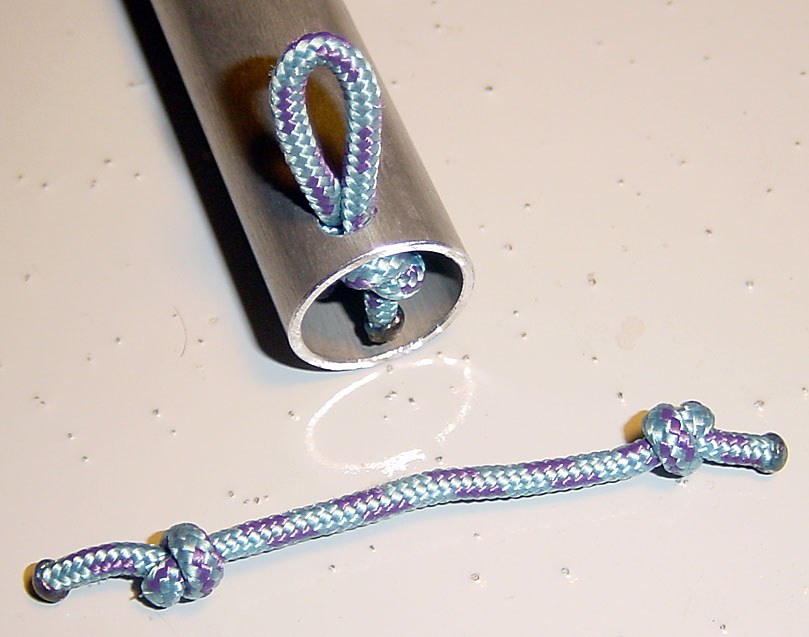
Bowline. The bowline forms a secure loop that will not jam and is easy to tie and untie (even after being loaded). The "Option" in the image, is for stiff lines submitted to shocks which could loosen the knot, but you can use it as an extra safety for this application after your length adjustment is finalized. |
Other Ideas / Main bar with built-in retraction system.
|
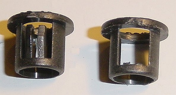
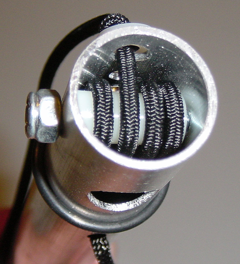
2005/6/23.
From the inside view, one can see the elastic bungee line going around
the internal end rollers then exit through the side hole.
Internally, along the length of the bar,
the bungee line goes back and forth as a single line
(facilitates replacement if ever needed).
The threading of the elastic bungee line is such that it rotates
in the same direction on the roller to reduce line-to-line friction there.
I used one for about 20 hours (then got a harness with built-in retraction system). 2 have been sold (I keep in contact and feedback is good). Although I believe that the burden of the retraction system should be inside the harness, having the retraction inside the main bar provides an option until most harnesses provide this utility. Aside from the obvious advantages during launching and landing (having bars always retracted, even after use) I hear that speedbars without a retraction system provide the risk of getting locked on the rear of the harness following a frontal collapse and remaining activated during recovery. |
|
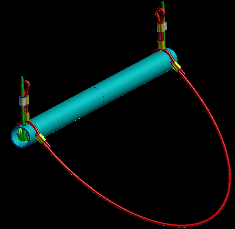
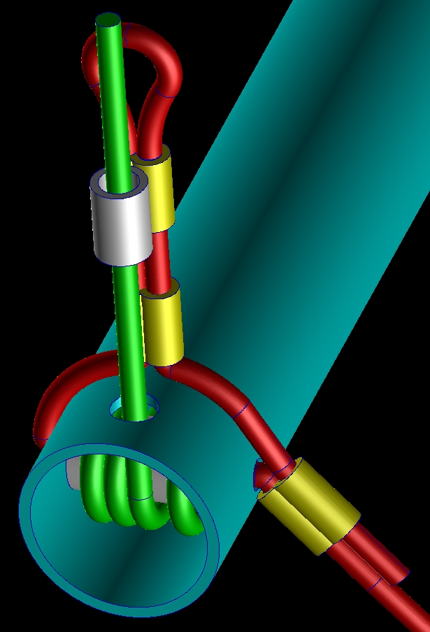
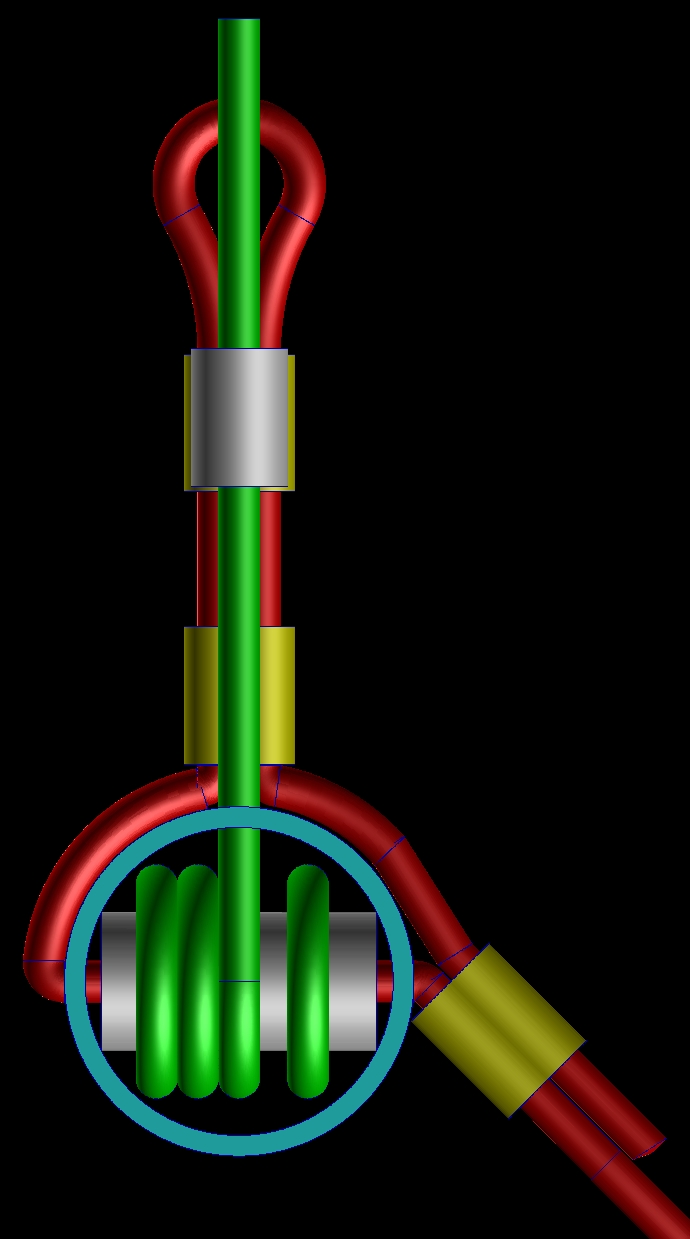
2005/7/25.
I prefer a rigid bar as the first step myself, but this is a conceptual design,
combining a self-retracting main bar, and a cable loop as a 1st step.
The 3 images are a graphic representation of the concept. Colors:
|
Other Ideas / First step with 3 fingers.
This bar has been strength tested, applying my full weight of 175 lb (more than double the real life load, due to accelerator line pullies and riser tension distribution) at the center of the bar with a single foot. There is a hole in the center of this bar, but it is strategically placed on the neutral axis (where the material is neither in tension or compression).
Open issues (highest priority first):
In flight.
|
2005/10/29. Relaxed flying at trim. Lower legs hanging with no effort. There is a light contact between the 1st step bar and the leg (not annoying). |
|
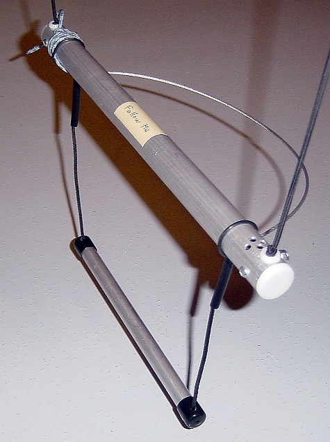
2005/10/29. Bringing forward my feet, so the 1st step hangs freely. 1st step bar is forward of its hand point by 4cm. Ignore the small quick-link between the main bar and the 1st step bar, it is only for me to quickly detatch the 1st step for more prototyping work. In its final state, the line from the first step will directly attach itself to the short loop (hidden in this picture) under the main bar. |
|
2005/10/29. Reaching for the 1st step by lifting one foot and bringing it down vertically. In this picture, the angle in the line between the bars show no pressure is yet applied, and that the bar naturally locates itself under the foot (the main goal). |
|
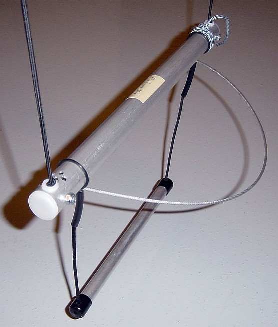
2005/10/29. Foot having found the first step. Light pressure appied (straight cord line between the bars). Notice the opening angle in the vertical finger to bar interface, confirming that the 1st step bar line hole is now aligned with the load path and this will allow the middle finger bar hole to be in the bending neutral axis, making that hole near stress-free at the bar center. |
|
2005/10/29. Fully extending the 1st step. Ignore the appearance of the end of the middle finger with a collection of dead weights wrapped with beige marking tape, a more esthetic dead weight will replace it. Getting the 2nd foot on the 1st step is easy. The camming effect of the main bar is not annoying partially thanks to its large diameter. Transitioning to the main bar is easy. |
Development pictures
|
Older design.
Since then, the rear-facing middle finger lays horizontal to optimize its leverage.
2005/10/23. In comparison to the System X (obsolete, but now available as the AIM speed bar). The system X had its first step about 2.5 cm forward from the vertical drop point. The J-Rod design is currently set at 4 cm forward. Ignore the clumsy weights added to the end of the center finger (work in progress). Both designs use a rear balancing weight, but this one can better leverage that "utility" rear weight. |
|
2005/10/25.
General picture of the first step mechanism.
Ignore the clumsy weights added to the end of the center finger (work in progress).
Total mass is 0.14 kg (5 oz), including the dead weights (2 quick-links) shown in this picture.
This design has the middle finger under more than double compression of the end fingers,
to match the torque induced by the 2 end fingers, and the center finger extra leverage (33% longer).
The side view shows the middle finger near horizontal, using its length for maximum leverage of the rear weight. 1st step bar is 4 cm forward of the vertical drop point. By comparison, the AIM speed bar is only forward by 2.5 cm. In-flight and ground handling testing will soon reveal if 4 cm is too much, in which case the length of all the fingers can easily be scaled back, and the rear dead weight could be further reduced. |
|
Older design.
Now the load lines hole are offset 30° from the fingers faces.
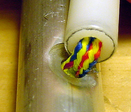
2005/10/23. One of the vertical fingers of the first step bar. It is made of a series of plastic tubes kept compressed by an internal bungee cord, which is doubled to also help alignement. Not sure how the small O-ring will stand up to the constant pull of the doubled bungee running inside the plastic tubes. I'm just concerned with rubber becoming brittle over time, so I will look for alternate maerials. |
|
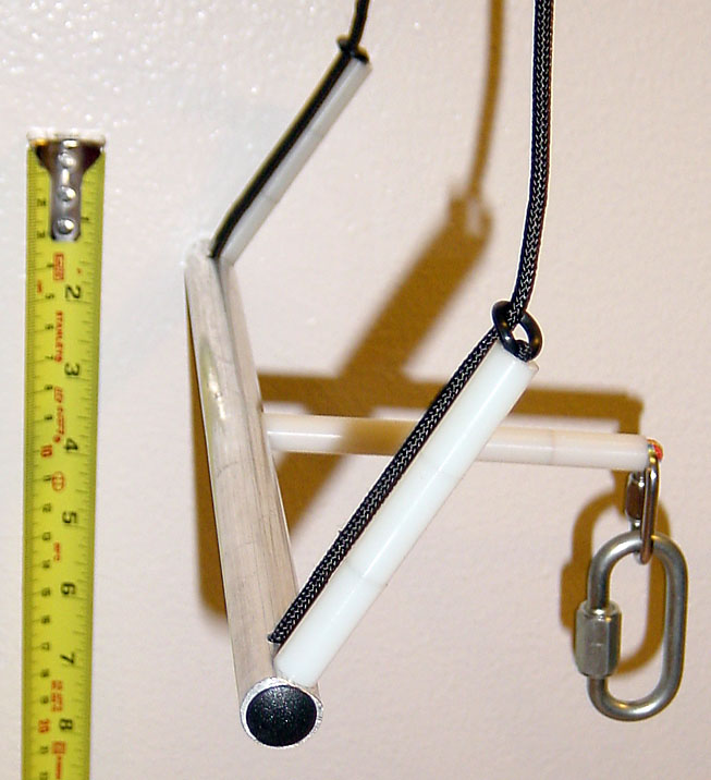
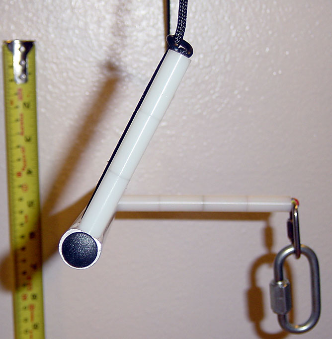
2005/10/25. The holes for the main line connecting the bars is set at 90° from the middle finger hole so that one remains in the bending moment neutral axis (almost stress-free). Once load is applied the end fingers re-align with the load line and we observe the pictured gap at the finger/tube interface. |
|
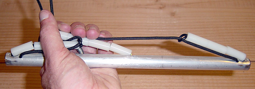
2005/10/25. Fingers collapsed (low DHV recovery I promise) into a near 1-dimensional space. Very low storage bulk, and unbreakable since it easily bends! |
|
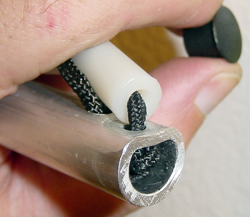
Older design.
Now the load lines hole are offset 30° from the fingers faces.
2005/10/23. Detail of the first step bar and finger interface at the end. A special deformation tool allowed to create a flat face, while avoiding ovalisation of the tube. For all finger interfaces: When bent at the bar, the internal elastic bungee cords slip out of the Nylon tubes, not from the metal bar. This way, the is less friction against the metal hole. The Nylon tube inner hole is less abrasive, and will prolong the life of the elastic bungee cords. |
|
2005/10/23. This is the tool that allows to press-deform a flat face onto the bar, while maintaining the round shape on the opposite side of the tube and avoid ovalisation. Bar deformation is controlled by a large vise. I spent a ridiculous amount of time designing this tool which now looks so simple. |
Fatigue test
|
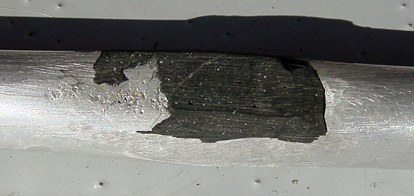
2005/10/27
The picture captures the appearance of the joint after being submitted to
1000 maximum flex/collapse motions (did it while watching TV),
all in the same bending direction (worst case for localised wear on the Nylon tube).
The 1000 cycle test represents the use of a recreational pilot (2 storage folds per week) over 10 years.
I was initially concerned (2005/10/26) with the sharp outer diameter edge of the tube
loosing its sharpness after a few bending motions.
The edge of the tube being slid under under load across the Aluminum flat face,
and passage over the edge of the metal hole seemed abrasive.
But after the edge starts getting a small radius, the process seems to stabilize
after about 200 cycles, not showing significant more abrasion after 1000 cycles.
Performing the test on the middle finger wich is more compressed by its internal bungee cords,
was also a worst case scenario.
2005/10/27. General: Detail of the first step bar and finger interface at the center. A special deformation tool allowed to create a flat face, while avoiding ovalisation of the tube. Although maximum bending is at the center of the bar, the hole is on the neutral axis (where the tension and compression stress and balanced). Wearing a shoe, I can put my whole weight (80 kg, 175 lb) on the center of this bar, having this hole in the neutral axis (determined by the structural hole position at the ends of the bar). |
|
2005/6/11.
The tongue on the main bar would lift the first bar (not just a cable loop)
as the first and main bars where connected by springy piano wire.
The tongue's angle was a friction fit, so it could be rotated for storage.
Apco's Wonder Bar
is another twist on the same tongue concept.
A couple things I disliked (I tested in flight) about a tongue:
|
|
2005/6/11.
I thought the idea of having the elastic bungee cord leaving the end at any angle would be good.
It is not a bad idea but adds complexity to the fabrication, and the tool to make that
nice inner radius costed 75$ (anybody needs it? I will sell cheap).
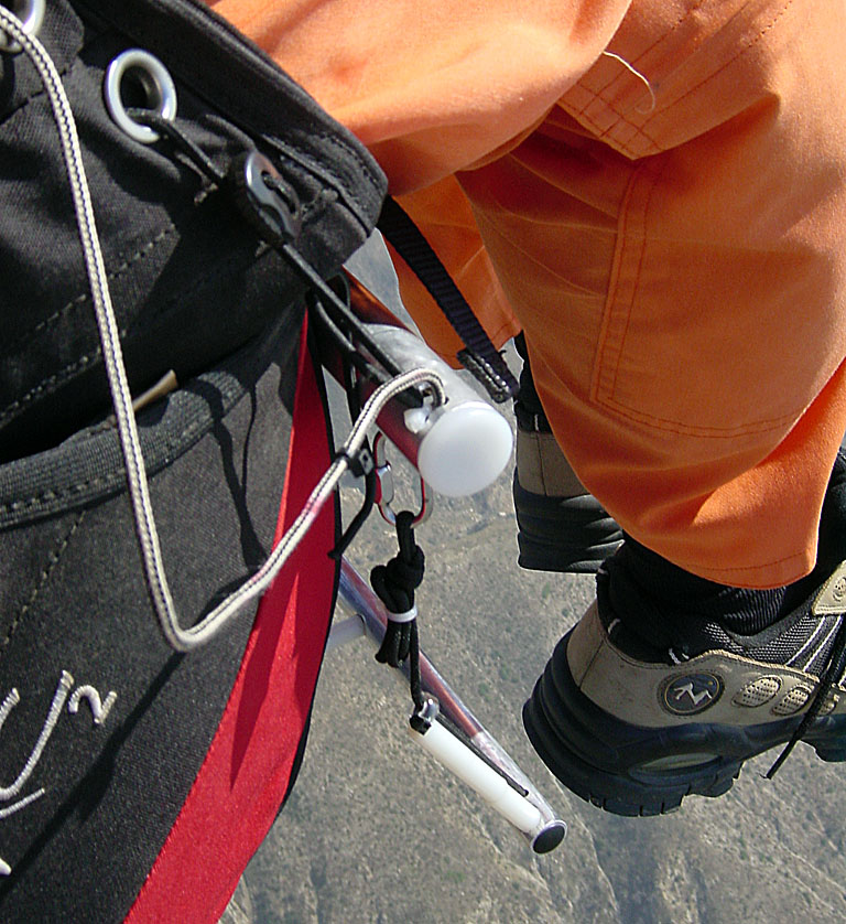
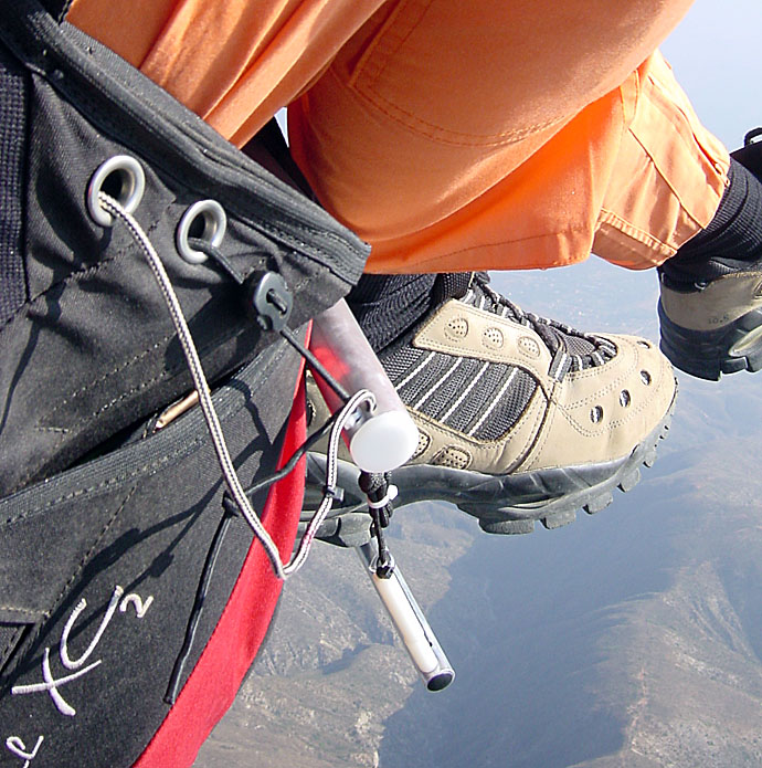
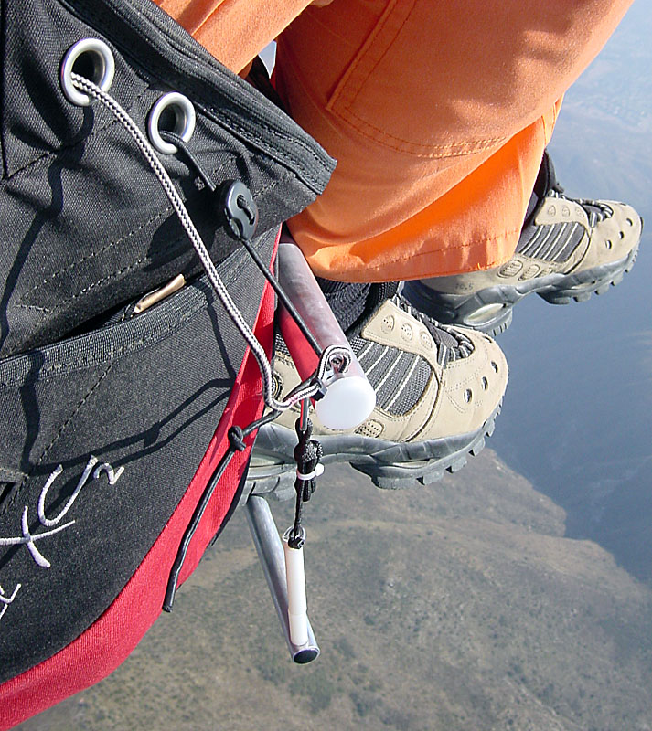
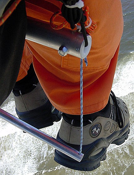
2005/6/18. The 3rd and 4th picture are in-flight testing of the ease to grab a vertically dangling bar. Notice that it is not being pushed back much by the airflow and rests behind the heals. About 20 hours of flying with a simple straight bar hanging vertically, allowed me to conclude there is a 75% chance to grabe the bar on the first try with one foot. Not too bad, and the worst case is that you will most likely get it on the second try. Once can also hit the bar backwards and catch it on the forward swing (is this acro?). |
|
2005/6/12. Cable connection between the bars. I thought of using thimbles for efficient cable connections. They look ugly. |
|
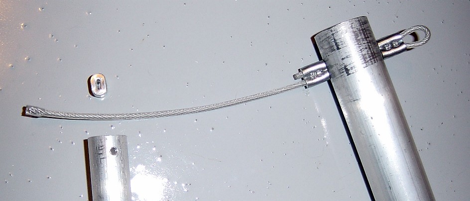
2005/6/19. I considered a cable stop and a simple ovalisation deformation on it. I know that a special tool is need for a proper swaging application: Swage-It, Nicopress. Just simple pinching of the cable stop proved that the special tool would be required as a good pull was able to dislodge it. Regardless, I prefer to avoid steel cables which can end up bent at a bar hole under storage. |
|
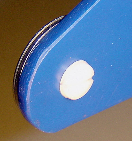
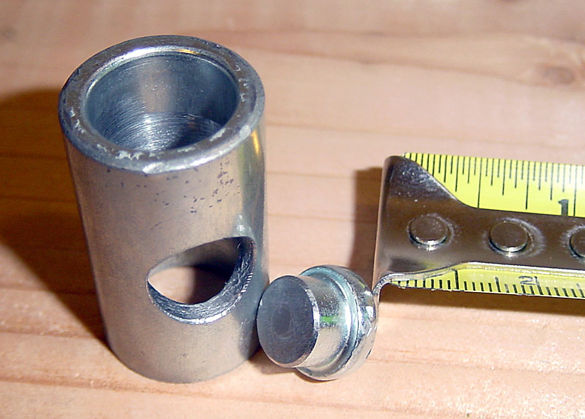
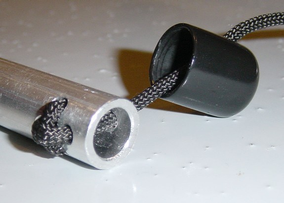
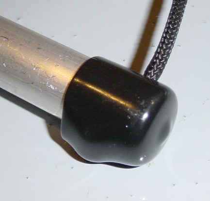
2005/6/23. One way to cap the 1st step bar. The rubber cap material makes it possible to remove it and adjust the X-lock line threading pattern to adjust the spacing between the bars, and it also prevents the line from slipping in the X-lock when no tension is in the line. |
|
2005/6/23.
The "X-lock", here first used on a main bar with built-in retraction system.
It is a novel way to attach the acelerator line to the main bar
without loosing line length for external knots
(image sequence is from left to right, then onto the next row).
This "X-lock" pattern has 3 advantages:
|
|
2005/7/17. 1st step forward displacement idea: A cable loop tongue allows to rotate forward a portion of the rope cable going down from the main bar. Either the loop tongue could use the harness to help it rotate (become harness shape dependant) or could be weighed at its rear-most point to use gravity (soft cable become a problem). An idea with merit, but I prefer to avoid steel cables which can get deformed in storage. |
|
2005/7/17. 1st step forward displacement idea. Use of semi-rigid cables, where a weight (not shown here) would be at the rear center of the loops and force forward by gravity the 1st step bar. This idea later put me on the path of the "finger" bar. |
|
2005/7/19. A small diameter piano wire runs along the length of the main bar and is held from rotation at its center, while its ends are bent to be aligned with a 1st step cable loop. I don't like cable loops as the 1st step, but wanted to explore the idea. The angle of the small diameter torsion rod is difficult to set, and should be mechanically controlled by stoppers at the start of the cable loop. The torsion rod, is vulnerable to deformation during storage. |
|
2005/10/19. Metal Epoxy to shape the surface of an Aluminum tube to create raised "flat spots". I used Loctite Epoxy for metals, and after roughing an Aluminum tube and doing a proper application with overnight cure, the rigid epoxy should be machined into a flat face. But using a rigid blade, I could flake off portions of the raised flat spot. Fear that long-time use of Exoxy on Aluminum would be unstable, I abandon this idea. |
|
2005/10/21. I tried finding a 5/8" square tube of aluminum with soft corners as the diagram show. Someone called it "unobtainium". I found stainless steel in this shape, did the math to see if it would be load-resistant enough and purchase a length. But the Stainless Steel tube was too heavy. The goal was to use the square shape for the "finger" bar idea so there would be no need to create flat spots at 90°. But I have found out since, that the angle between the flat spot to the fingers should not be at right angles. So no need for square tubes. |
|
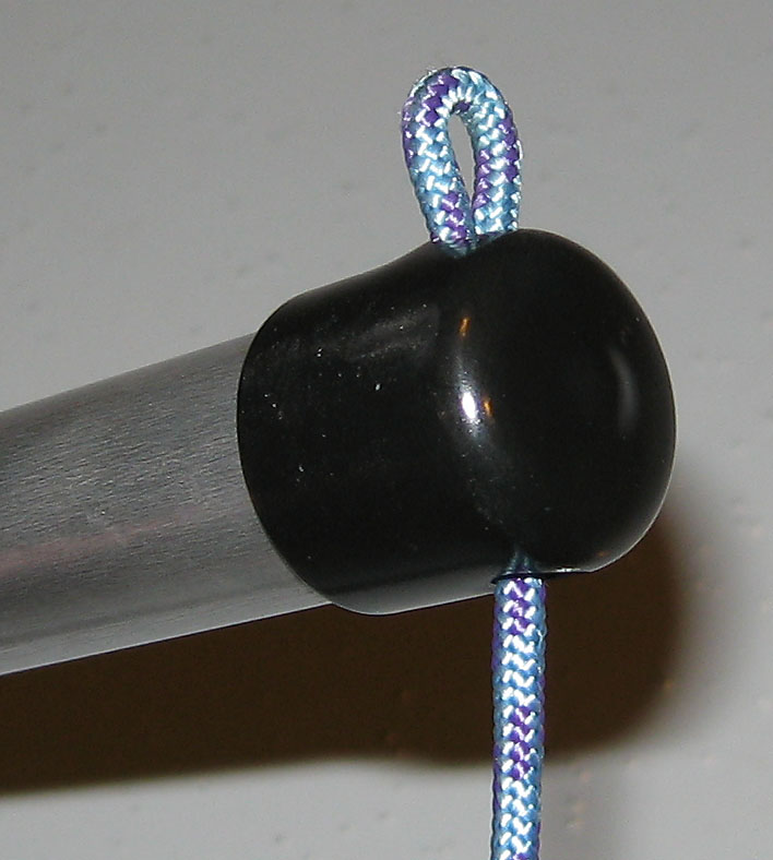
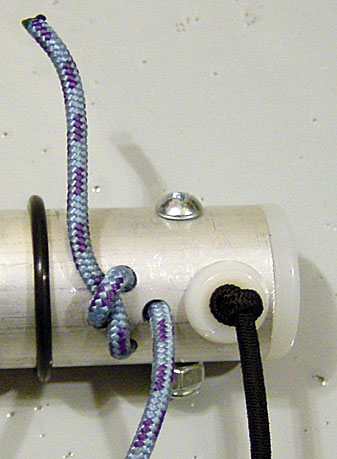
2005/10/30. Loop used to attach the line coming from the 1st bar. The line from the first bar will use a Non-slip loop knot on this loop. The quick-link in this picture is just for my personal testing allowing for quick disconnection. Inside the bar, the loop is held by 2 knots (one for each side) plus an extra set of backup knots. All these knots have been pre-tensioned, so this loop with not lengthen under load. |
|
2005/10/30. Stuff the end of the line inside the bar, and plug the bar end with the end cap. Ignore the patch of duct tape covering an unnecessary test hole. Also, the small white cable tie used to crimp the elastic bugee cord, may not be final. |
|
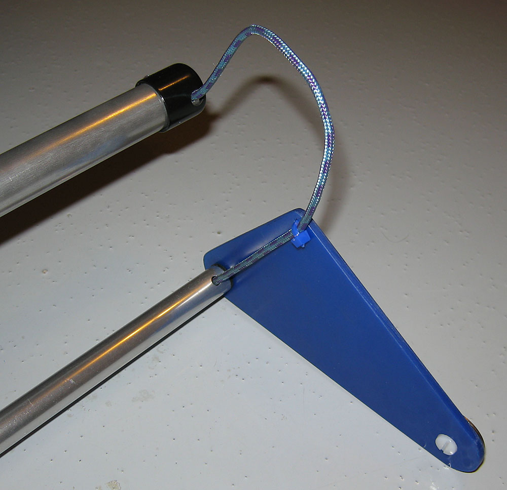
2005/11/1. Early prototype. 1st step bar is balanced 4 cm forward from its hang point, by a counterweight at the end of the fins (blue). A simple solution was found to prevent the fins to rotate about the bar's axis: A knot is added after the loop holding the bar connection cord, limiting the amount of cord which can be rolled around the bar. The fins are held perpendicular to the bar, by a light tension from an elastic bungee inside the length of the bar. The width of the bungee loop holding the fin, alows it to auto-center itself with the bar's inside diameter. To prevent abrasion of the fin from the Aluminum bar, a washer is placed in between. I am considering adding Nylon "snap-in bushing"s (I have seen those at my favorite hardware store) to reduce friction during fin collapse, of the elastic bungee at inside edge of the bar ends. The washers used for counterweight are just an initial idea (although not a bad idea). This design is much easier to fabricate than the First step with 3 fingers and does not require to make a hole or deform the center of the bar (stronger). Over-designed for strength, there is room for weight reduction, and effect would be doubled by a matching reduction of counterweights. The current design only weighs 9 oz (250 g) including counterweights. |
|
2005/11/1. Early prototype. Detail of an end fin. I just cutout the shapes from a rigid plastic clipboard. Not sure if this is the ideal material, althouth not a bad choice at the moment: Very light for its rigidity (need to be cut with a hacksaw), and does not shatter. These end fins also serve a protection purpose: Cut with a larger radius than the metal bar, it offers a greater contact area in the event of leg contact when pinching the bar between the legs while running. This is better than having a rubber cap at the bar ends. These fins have a low frontal area, not contributing to significant drag. The elastic bungees cords holding the finds perpendicular, do not have to counteract the weight of a cantilever part, as was the case with the First step with 3 fingers, but only to stabilise the fins. I can see a cool logo go on these fins. Maybe the final design will have a cutout to reduce fin mass (although already light). |
|
2005/11/1. Early prototype. View of the collapsed fins, for storage purposes. By laying the main bar next to this bar, we have a compact package for storage which should be resistant to handling abuse. The elastic bungee cord holding the fins has extra extension margin. I may use a stronger bunge cord in the next iteration, although this one seems acceptable. |
|
2005/12/8.
Shape B + Blue clipboard plastic (0.133" thick).
Good:
|
|
2005/12/7.
Shape B + White translucid binder plastic (0.080" thick).
Good:
|
|
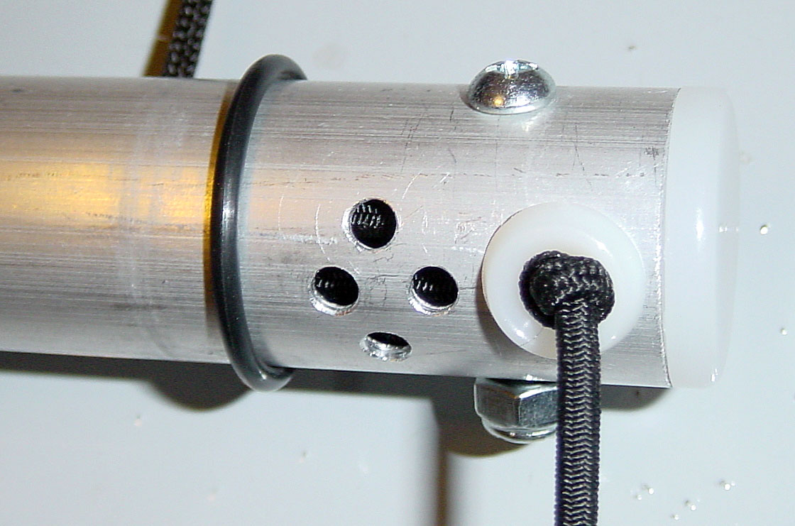
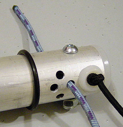
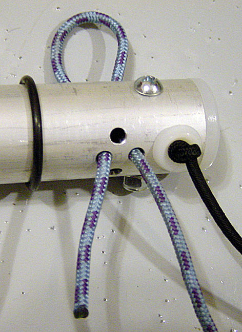
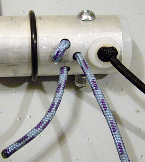
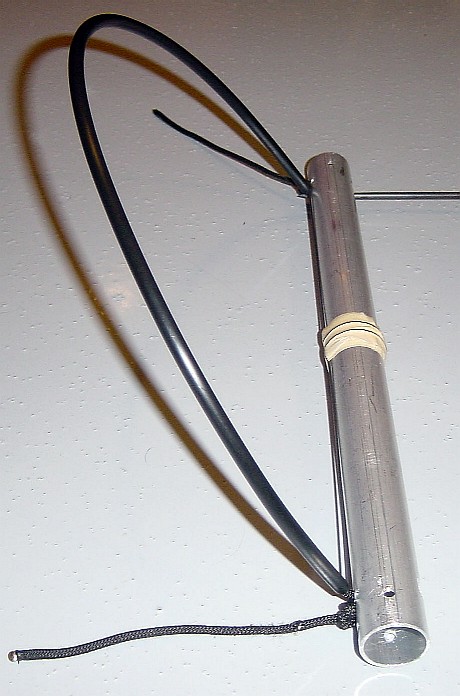
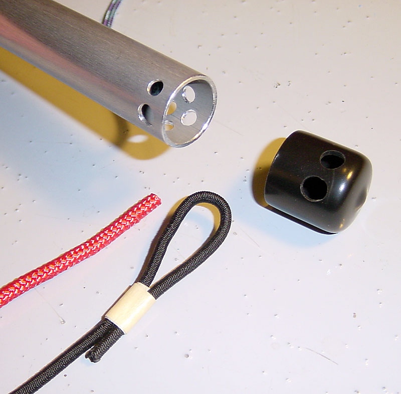
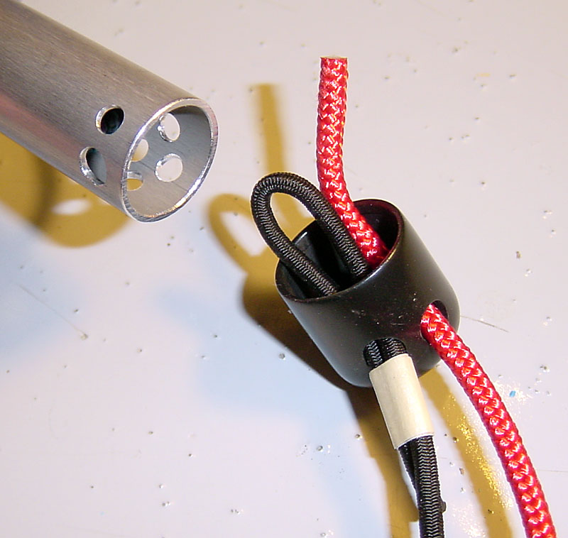
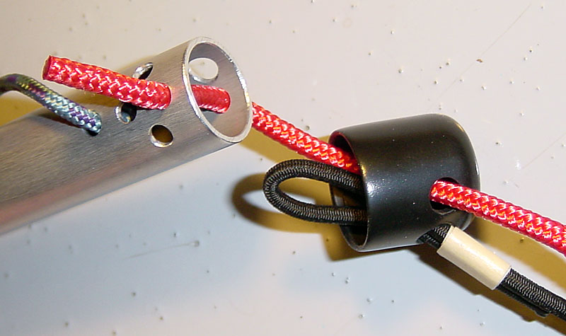
2005/12/14.
Accelerator line X-Lock + Bungee loop is locked inside by accelerator line.
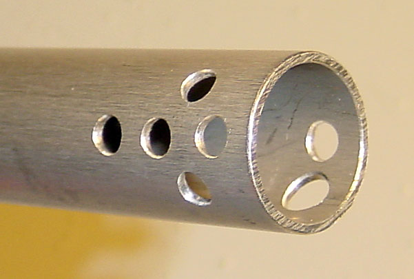
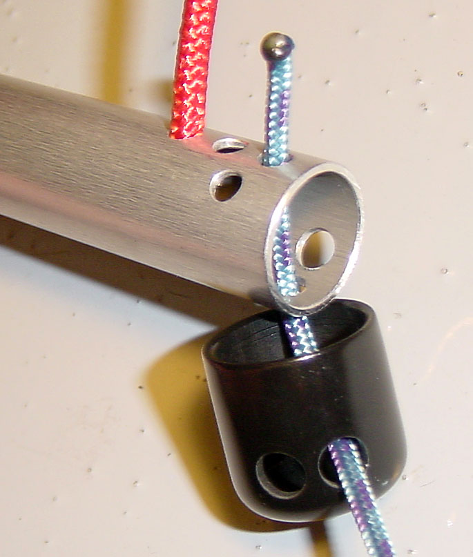
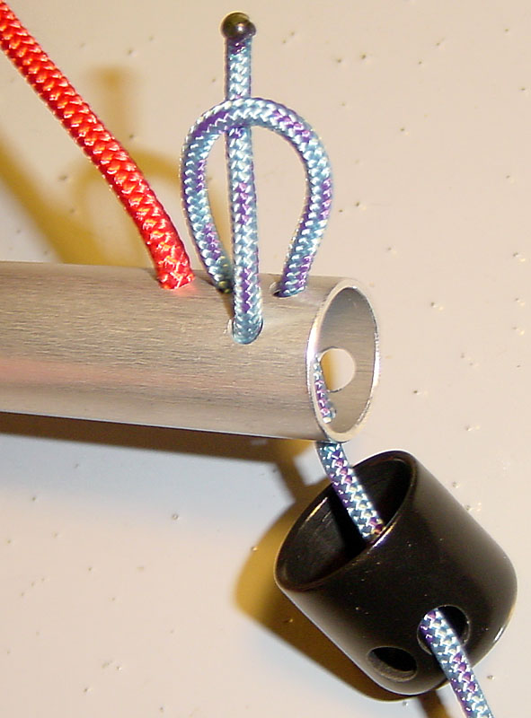
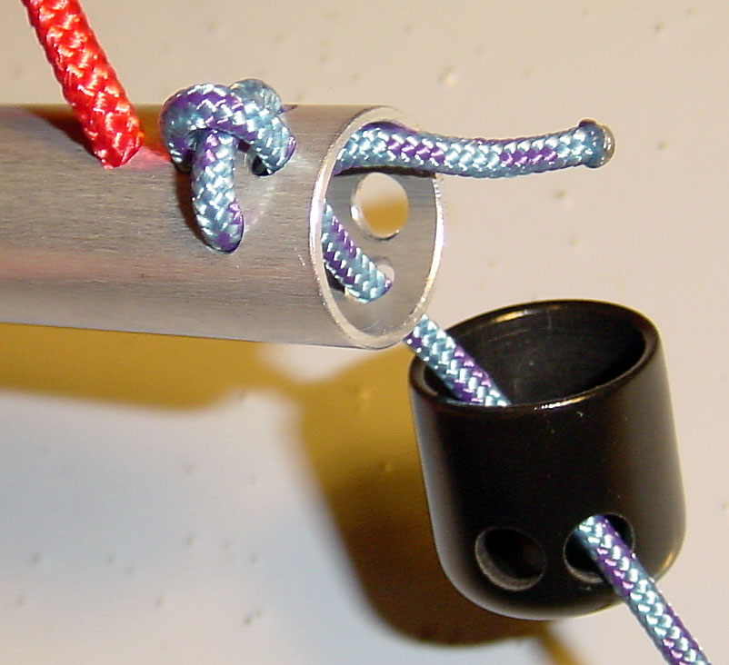
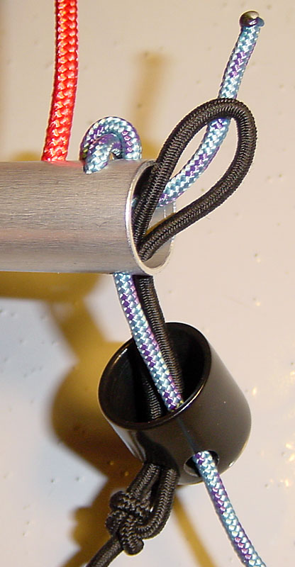
See comparison study in: Main bar interface with harness lines. The blue line connects the main bar to the first step bar. The black line is loop of elastic bungee of 1/8" (about 3 mm) used to retract the main bar to the harness. A tape was used to illustrate that a loop must be made at end end of the line. It is the responsibility of the pilot to decide how this loop is achieved: I recommend not doing a knot which will be hard to undo, instead consider a series of cable ties (which can be cut and replaced). The red line is the accelerator line going to the risers. In this case, it is at the maximum diameter of 4 mm (3 mm recommended). The black cap, with 2 holes, is used for: Leg and equipment protection, dust cap, accelerator line X-Lock consolidator (so it cannot slip when unloaded). 1) Thread the red accelerator line through the upper black cap hole. 2) Thread the black bungee line loop through the lower black cap hole. The black bungee line loop will have to later thread through the largest bar hole. 3) Thread the red accelerator line through the smallest of the 2 ajoining holes, then out the X-Lock (patter of 4 holes) hole closest to the bar end. 4) Thread the red accelerator line back into the bar using the furthest X-Lock hole, and out one another X-Lock hole. 5) Pass underneath the first bend, which will avoid the most loaded part of the line to rub against the edges of the metal holes. 6) Thread the red accelerator line back into the bar through the remaining X-Lock hole, and out the end. 7) Thread the black bungee line loop through the last (and largest) hole into the bar. 8) Lock the black bungee line loop by passing through it, the red accelerator line. 9) Tighten the red accelerator line on its X-Lock and send the excess line into the middle of the bar. 10) Pull tight (towards the outside) the black bungee line loop. 11) Slip the black cap onto the bar end, making sure to cover the lines looping in the X-Lock, which will prevent slipage when the line is unloaded. |
|
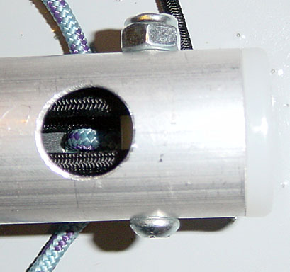
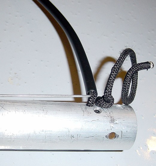
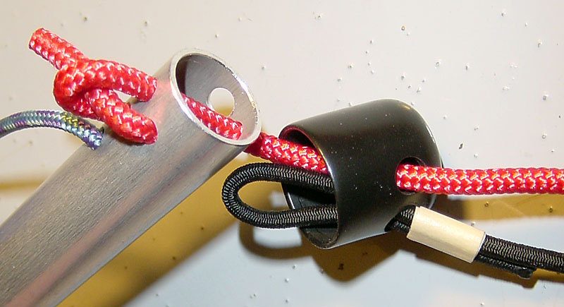
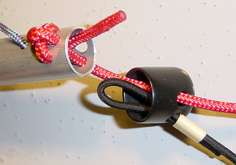
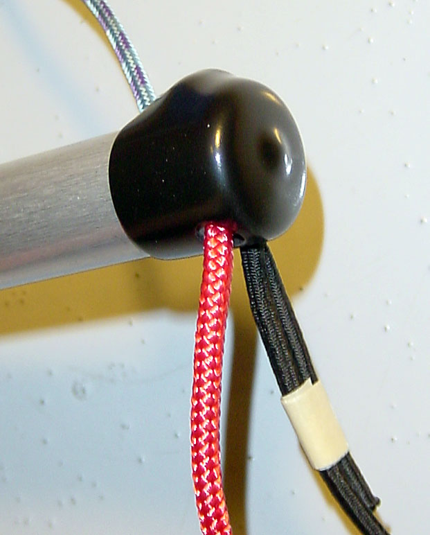
2005/12/26.
Accelerator line X-Lock + Bungee loop is locked inside by accelerator line square knot.
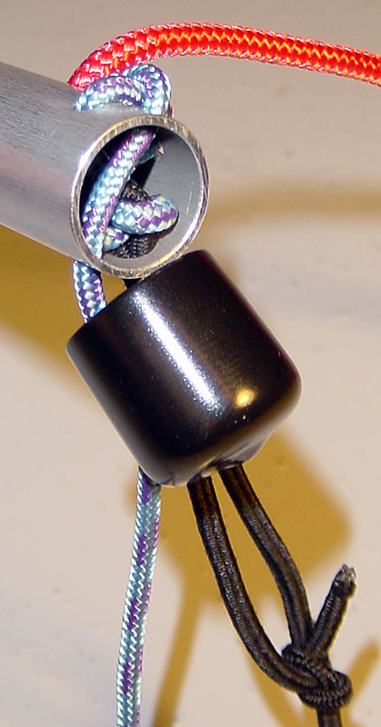
See comparison study in: Main bar interface with harness lines. The red line connects the main bar to the first step bar. The black line is loop of elastic bungee of 1/8" (about 3 mm) used to retract the main bar to the harness. A Bowline is used to create a loop at end end of the line. The blue line is the accelerator line going to the risers. In this case, it has a diameter of 3 mm (recommended). The black cap, with 2 holes, is used for: Leg and equipment protection, dust cap, accelerator line X-Lock consolidator (so it cannot slip when unloaded). Construction notes: Hole pattern (drawn on masking tape) for side with 5 holes: All 5/32" dia holes, aligned holes centers are 5, 12.5, 20 mm from bar edge, pair of holes centers at 8.75 mm from bar edge are 12 mm centers apart. On other side, one of the hole (for accelerator line) is a continuation of the one on opposite side closest to edge. The other hole (for bungee loop) is 13/64" diameter (the only one of that diameter on this bar), and made at a 45° angle with same hole edge distance from bar edge as the adjoining hole. 1) Thread the blue accelerator line through the upper black cap hole, the through the smallest of the 2 ajoining holes, then out the X-Lock (patter of 4 holes) hole closest to the bar end. 2) Thread the blue accelerator line back into the bar using the furthest X-Lock hole, and out one another X-Lock hole. Pass underneath the first bend, which will avoid the most loaded part of the line to rub against the edges of the metal holes. 3) Thread the blue accelerator line back into the bar through the remaining X-Lock hole, and out the end. 4) Thread the black bungee line loop through the lower black cap hole, then through the last (and largest) hole into the bar. 5) Lock the black bungee line loop by passing through it, the blue accelerator line, forming a square knot. It is important to create a square knot so we do not rely on the hole edge friction to block the line from exiting the bar, which would accelerated the wear on the bungee sheathing. 6) Tighten the black bungee line loop square knot with the blue accelerator line and pull it to its final location. 7) Tighten the blue accelerator line on its X-Lock and send the excess line into the middle of the bar. Slip the black cap onto the bar end, making sure to cover the lines looping in the X-Lock, which will prevent slipage when the line is unloaded. |
Blog.
| 2005/2/15 | Around this date, I starting designing main bars with self-retraction system, as the harness I had at the time, had no built-in speedbar retraction system. |
| 2005/5/1 | Now having a harness with built-in speedbar retraction system and in need of a new speedbar, I started focussing on a better 2-step speedbar with easy foot-grab of the 1st step. Discussion on ParaglidingForum. |
| 2005/10/24 | First step with 3 fingers: The longer single center finger can not support as much torque as the sum of the 2 end fingers. This is because it uses the same elastic tension inside it, and is disadvantaged by its longer length and lesser count (one finger matching the torque of 2). |
| 2005/10/25 |
First step with 3 fingers:
Good ideas... 1) Center finger angle. Center finger should not be at 90° of the end fingers, but more around 60°. That way, the center finger will have max leverage when the end fingers are rotated 30°. It would allow the length of the middle finger to be reduced about 13% [1-cos(30°)], or generate more usefull torque from the same dead weight. The bar's center hole can still be on the neutral axis (where there is no tension or compression as a result of a bending load) by setting the end holes for the cords going to the main bar, at a 90° angle from the center hole, or 30° ahead of the end fingers. 2) Increased finger compression. The end fingers use 2 strands of 1/8" (about 3 mm) elastic bungee cord, as did the center finger. I was successful in fitting 2 stands of 4 mm bungee cord, which also has a sheathing allowing for more extension (about +200% instead of +100%). When at about 90% of its maximum extended length, 2 cords of the 1/8" bungee have a total tension of 1.44 kg, while 2 cords of the 4 mm bunger generate 3.50 kg (more than double). So it is very feasible to increase the middle finger compression this way and the middle finger can be made to surpass the torque load of the 2 other end fingers. Another way is to pass 3 strands of the 1/8" bungee, but that would not increase the compression as much. 3) Increase middle finger diameter. Possible but would require re-tooling to deform a larger face of the aluminum tube at its center (not a good thing to do since that is a critical bending strength area). No need for this at this time, since increasing finger compression seems like an easier solution. |
| 2005/10/25 | First step with 3 fingers: Good progress. I did a new prototype of the first step finger bar, and it is mechanically near perfect. This one has the center finger at 60° from the end fingers, a boosted middle finger compression to match the torque capacite of the 2 others, and structural cable holes at 90° from the center hole (so it is in the bending neutral axis). And when it hangs, the middle finger is near horizontal, optimizing its leverage. Total mass is 0.14 kg (5 oz), including the dead weights (currently using a small and a large quick-link). Pictures of 1st step bar updated. |
| 2005/10/26 |
First step with 3 fingers:
|
| 2005/10/28 | Main Bar: Good progress. Had good ideas to make a main bar that is simple to build, offers easy connection to the harness retraction bungee cord, and allows easy threading an accelerator line length adjustment. |
| 2005/10/29 |
First step with 3 fingers:
First flight:
Observations:
|
| 2005/11/1 | First step - "End fins" concept. I will prototype a different approach to achieve the same goal of balancing the 1st step forward. A simple bar with ends used by vertices of soft triangular fins, used to balance the bar forward. The soft fins would collapse onto the bar for storage. This could be much simpler than the "finger" bar, and simultaneously create bar end padding in case of leg contact. |
| 2005/11/2 |
Proof of concept (rough prototype) done for the First step - "End fins" concept.
Purchased more parts today, to make a better prototype.
Excel spreadsheet referenced in the Market Comparison has been updated. |
| 2005/11/4 | Chose a new line material for connecting the 1st step to the main bar. The new line has more abrasion resistance (thicker sheathing), no sheathing slippage issue, and has a safety facor of about 7: Line can support about 200 lb tension with knots (400 lb rating), and line only need to support about 30 lb (half of about a third the pilot's weight). |
| 2005/11/4 | Ready-for-flight prototype of the "End fins" concept. 1st bar is 4 cm forward of hang points. Mass of 0.32 kg (11.3 oz), including both bars and 1st step counterweights. |
| 2005/11/5 | Favored 1st step concept: "End fins". Preferred over the previous First step with 3 fingers. |
| 2005/11/6 | Creation of a decision matrix (Excel spreadsheet) to find the best way to connect the line from to the main bar onto the 1st step's bar. |
| 2005/11/7 | Document revisions, and setting a clear path of remaining action items. |
| 2005/11/9 | With the use of a Decision matrix (Excel spreadsheet), the best way to connect the line from to the main bar onto the 1st step's bar was found: The "Simple_InOut_2" concept (picture). |
| 2005/11/11 | With the use of a Decision matrix (Excel spreadsheet) the best way to compress/center the end fins onto the bar ends was found: The "SingleBungee_OutInFin" concept (schematic drawing). |
| 2005/11/13 |
First Step:
First flight:
Using an early prototype (does not have the optimal load line connection knot,
the final bungee knot configuration, or the optimized fin shape),
a very encouraging day:
|
| 2005/11/15 | Considering locally available materials. Creation of a spreadsheet to compare materials and tube sections: Bar Material Selection (Excel spreadsheet). |
| 2005/11/16 | Doing a test on currently used Aluminum tube reveiled a 293 MPa stress yield limit. Not bad considering the highest values (7075 alloys) are around 500 MPa. My guess is that the tubes I have now are 6061-T6 Aluminum, rated at 275 MPa (typical). |
| 2005/11/16 | Based on Bar Material Selection (Excel spreadsheet), if I were to switch to a 7075 alloy, I could save about 30% of the total weight (considering the 1st bar counterweight reduction). This seems worthwile, so I will try to find a supplier. |
| 2005/11/17 | Rejecting composite tubes. I was considering fiberglass (and composites in general) tubes (Max-Gain), but I do not like the thought of machining holes to accomodate the design (4 holes in first step bar, 10 in the main) and how those holes will withstand the lines trying to pry them open to pull a knot through, just where the material has been weakened from the machining operations (damaged fibers and matrix). A different approach to line connections and considerable re-design would be required. Also, machining composite materials is a dirty job (I have a background in composites). |
| 2005/11/17 |
I found suppliers (
American International Metals +
Metal Express)
for 7075 Aluminum tube in these sizes:
1/2" and 3/4" OD, 0.035" wall.
But the minimum order is about 400 $ to account for the minimum 12' ordering lengths.
Expensive just for getting a few feet for building a prototype,
but OK later if I use all the purchased lengths for production.
The price of 7075 Aluminum tube (about 25$ worth for first+main bars in each set)
should not be a deterrant in comparison to the price of workmanships to build the bars,
and may contribute to a "coolness" factor when feeling the super-light bars.
Weight savings. I updated the Bar Material Selection (Excel spreadsheet) to see if those thinner wall thicknesses would be OK, and they would be: Safety factor of 3.0 for the first step (less critical if fails), 4.1 on the main bar. This could be the perfect material, I just need to decide on spending 400$ to build a better prototype using it, and having the extra material in stock for making more speedbars. I'm wondering if I should set an early-adopter pre-order price to help me get the ball rolling with optimized materials. I like the idea that 5.2 oz could be saved: 46 % of the total weight (from 11.3 to 6.1 oz). This is starting to compare well with other designs (example: 7.7 oz for System X). |
| 2005/11/18 | First bar material selection. I found a better compromise between safety factor, weight and cost: Bar Material Selection (Excel spreadsheet). The first step bar will be changed to 2024-T3 Aluminum, 0.5" OD, 0.065" wall. I expect a weight saving of 2 oz. I will need to re-design the Nylon end fitting and fabrication. |
| 2005/11/19 | Main bar material selection. I found a better compromise between safety factor, weight and cost: Bar Material Selection (Excel spreadsheet). The main bar will be changed to 2024-T3 Aluminum, 0.75" OD, 0.065" wall. I expect a weight saving of 0.9 oz. |
| 2005/11/21 |
Main bar material.
Got the new bar material: 3/4" OD, 0.065" wall, 2024-T3.
Main bar end caps. I'm thinking that an external thin/soft cap (instead of an internal end plug), would serve double-purpose to secure the lines threaded through the X-Lock. Similar to what I had done in a past for a 1st step which had an X-Lock (Pictures: Cap OFF + Cap ON ). |
| 2005/11/22 | First bar material. I received the first bar material. |
| 2005/11/23 | Found missing parts. I found/purchased candidate Nylon parts for 1st bar ends, and end caps for the main bar (I have a choice of external and internal to try). |
| 2005/11/24 | Main bar length. Revised length is 27.5 cm, 10.5 cm less than before. For related information see Research and development. Bar Material Selection (Excel spreadsheet) was updated for the change. |
| 2005/11/24 | First step bar end "snap-in bushing". Using Nylon spacers (0.5" OD, .194" ID, 0.5" long) I sucessfully reduced the OD to 0.364" for all but a 2 mm remaining flange, so it slides into the Aluminum tube without play until its flange. I used a lathe cutting tool and my drill press to achieve this, using a machine head bolt (hex) with spacers holding the Nylon spacers during machining. The result is satisfying, and the Nylon ID allows to pass the 4 mm bungee (unloaded) easily. |
| 2005/11/27 | First step bar: Connections. I found a more satisfying solution to attach the load line, and secure the fins. More esthetic (no apparent bungee line knot), easier to fabricate (off-the-shelf "snap-in bushing" for bar end), and potentially stronger. Also, there would be no longer a need for a mid knot in the load line, to prevent the fin from rotating by compressing the fin. |
| 2005/11/28 | Anodized finish. I tested the scratch finish resistance of anodized Aluminum tubes. Not good: Scuff marks add up quickly, and deeper scratches are accentuated by the color contrast. |
| 2005/11/28 | Main bar material selection. I found a better compromise: Bar Material Selection (Excel spreadsheet). The main bar will be changed to 2024-T3 Aluminum, 0.75" OD, 0.049" wall. I expect an additional weight saving of 0.5 oz. |
| 2005/11/29 | Main bar material. I now have some 3/4" OD, 0.049" wall, 2024-T3 Aluminum tube. |
| 2005/11/30 | First step: Fin weight. I measured the exact weight of the clipboard panel material (3.57 kg/m2). In my early prototype, I used about 1/3 of a (22.5 x 31.75 cm) board, which results in 85 g (3.0 oz). That is a significant portion (45%) of the currently predicted total weight (7.0 oz). The fins will go on a diet as part of their re-design. |
| 2005/12/2 | First step: Fin math. Established the equations between the dimension variables. See Fin design. Selected dimensions: 4.0 cm forward first bar, with Theta = 35°. |
| 2005/12/5 | First step: Fin material. Purchased a few plastic materials in a quest to either replace, or be bonded to, the existing thick+rigid blue clipboard plastic (0.133" thick). Using "Krazy Glue" nothing would bond to each other, so either a different adhesive, or mechanical fasteners will allow to join them. One of the new materials (0.080" thick) is 60% of the thickness and seems rigid+compliant enough, so it could serve as a single material to make the fin. |
| 2005/12/6 | First step: Fin design. Established better design parameters: Fin design. |
| 2005/12/7 | First step: Fin design. Pictures added under Fin design. |
| 2005/12/8 | First step: Fin design: Upper line fixation. Two 3/32" holes, separated (center axis) by 4.5 mm, allow the passage of a 3/32" width cable tie (3" long, rated at 18 lb), to hold the line passage position. Load line slip is allowed with some friction. |
| 2005/12/9 | First step: Fin design: Revised planar parameters. |
| 2005/12/10 |
First Almost-Ready prototype.
Built a new prototype with all the latest design changes.
Needed counterweight is established at 14 g (0.5 oz).
Only need to finalize the counterweight type and fixation.
Pictures taken
(See First Step and Main Bar),
as well as a movie of the fin deployment from their storage position
(under First Step).
Total weight is only 165 g (5.8 oz). This is better than my expectation. 2024-T3 Aluminum finish. Using "Blue Magic" Liquid Metal Polish makes the dull bars shine. |
| 2005/12/12 | 1st step counterweight. Found a potential solution with Stainless Steel fender washers. New requirement: Avoid metal-metal contact of moving parts (bolt head <-> bar). |
| 2005/12/13 |
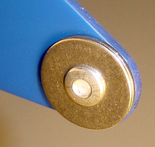
1st step counterweight.
Selected materials: Stainless Steel fender washers: 1" OD, 7/32" (nominal 3/16") ID, 0.045" thick.
2 washers for each fin.
Main bar: Good idea: Use the excess accelerator line to lock the bungee loop, instead of its first passage through the bar, avoiding friction motion. |
| 2005/12/14 |
1st step counterweight.
I have found an excellent fixation method.
Only plastic will contact the bar, and only one hole needs to be made in the fin.
And it looks clean.
Added a graphical explanation of why just having the first step a bit forward helps so much to grab it. Made an updated series of pictures for the main bar connections. |
| 2005/12/15 |
1st step end fins.
Added the planar shape dimension schematic:
Image.
Selected a counterweight fixation method ( Outside picture, Inside picture ), and updated the prototype. Design is done and I built a unit for myself A purchase Price has been set. |
| 2005/12/17 | Main bar. The Main bar interface with harness lines needs improvement. The bungee line from the harness was submitted to excessive wear. Until I find the ideal interface, I eliminated the bungee line abrasion by modifying my latest protype to have an external loop to attach the bungee line: Picture. |
| 2005/12/18 | Main bar. Selected a better Main bar interface with harness lines. Reduced Price thanks to less manufacturing time: Single hole instead of 5 for an X-Lock. Completion of the Build It Yourself and Installation instructions. |
| 2005/12/19 | Enhanced the Build It Yourself instructions. Providing more details on part suppliers in the USA and Europe. |
| 2005/12/26 | Although there is no design change, I documented an option: Accelerator line X-Lock + Bungee loop is locked inside by accelerator line square knot. Satisfaction is achieved when knowing all options have been explored. |
| 2005/12/27 | Minor improvement reflected in the Procedure to build a unit: The lines leaving the main bar (towards the first bar) are moved closer to the end of the main bar ends. This allows for a linear increase in the line separation between the bars, so the fins do not need to compensate for any side load. It wasn't a problem before, as the fins had enough compression load to over-compensate the small side load at the top of the fin, but we may as well make this design perfect. |
| 2006/4/16 | Feedback is a new section of this web page. |
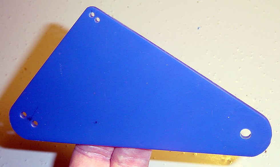
| 2006/10/27 | End Fin template. Creation of a template (made from a plastic sheet) to easily sketch the contour of an End Fin and hole locations. |
| 2006/11/24 | First client: Richard Hammer. Delivery of the 1st unit. |
| 2006/11/28 | Testing tools to fabricate the fins. Thanks to Rob von Zabern for using his water-jet cutting machine, as it made an easy job of cutting the outer shape of the fins. Also, thanks to Don Mies for having me test cutting fins on his scroll saw, which proved it was not an appropriate tool (melts the fins). |
| 2007/2/7 | Second client: Mark Harrah. |
| 2007/2/15 | Real-life testing. 126 hours airtime with the 2005/12/18 version. So far so good: No sign of accelerated wear, good usage behavior. Abuse resistance: Speedbar was used many times to induce full-speedbar collapses during wing tests, which make it snap back against the harness. I stepped on it once or twice while setting up my gear. I banged it between my legs while running (first bar fins leg protection does work). Picture of April 15, 2006. |
| 2007/2/16 | No EBE here: I want to reassure everyone that the development of the J-Rod is not linked in any way to reverse Engineering of extra-terrestrial technology (reference). |
| 2007/2/17 |
First step: Fin material: Lexan.
2 weeks ago, pilot Joe De Briyn showed me his self-built unit:
Picture.
He used and suggested using Lexan
for the plastic fins, also giving me a sample I can test to destruction.
I am starting to like Lexan.
It's tough stuff and remains transparent until failure (no opaque whitening when bent).
Common uses of Lexan: Aircraft canopies, windscreens and other windows. Household items: Bottles, compact discs, and DVDs. Bullet-resistant glass. At the movies: Featured on Star Trek IV and described as "transparent aluminum". |
| 2007/2/19 | Video of in-flight use. There is a new video added, showing an in-flight activation. See First step features. |
| 2007/3/3 | Feedback from James Bradley. |